Surely RF Isn’t That Hard…
Over the years my obsession with sensing my environment has only deepened with the advent of new sensors and/or the availability of them to Makers.
The BME280 from Bosch got my attention because of its ability to measure temperature, humidity and pressure in a rather small (albeit expensive) form factor.
At the time I was playing around with the RFM69 ISM band radio modules from HopeRF and one evening I said to myself “I could make a wireless sensor, surely RF isn’t that hard”. I fired up Eagle and set to work designing a PCB, all the time thinking about the form factor, did I want a shield for an Arduino Uno? How was I going to power it? What Antenna was I going to use?
I have often designed a PCB first then designed an enclosure to 3D print on my Ultimaker2, the results were always satisfactory but not quite “Consumer Grade” and knowing my better-half’s dislike of my projects spread strategically around the house I knew it had to look good if I was to have a few scattered around in different rooms.
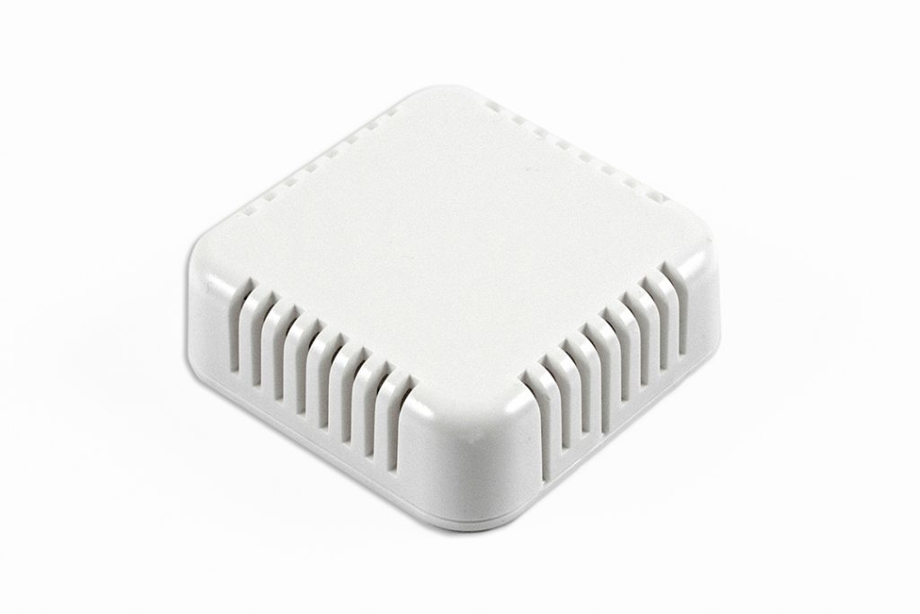
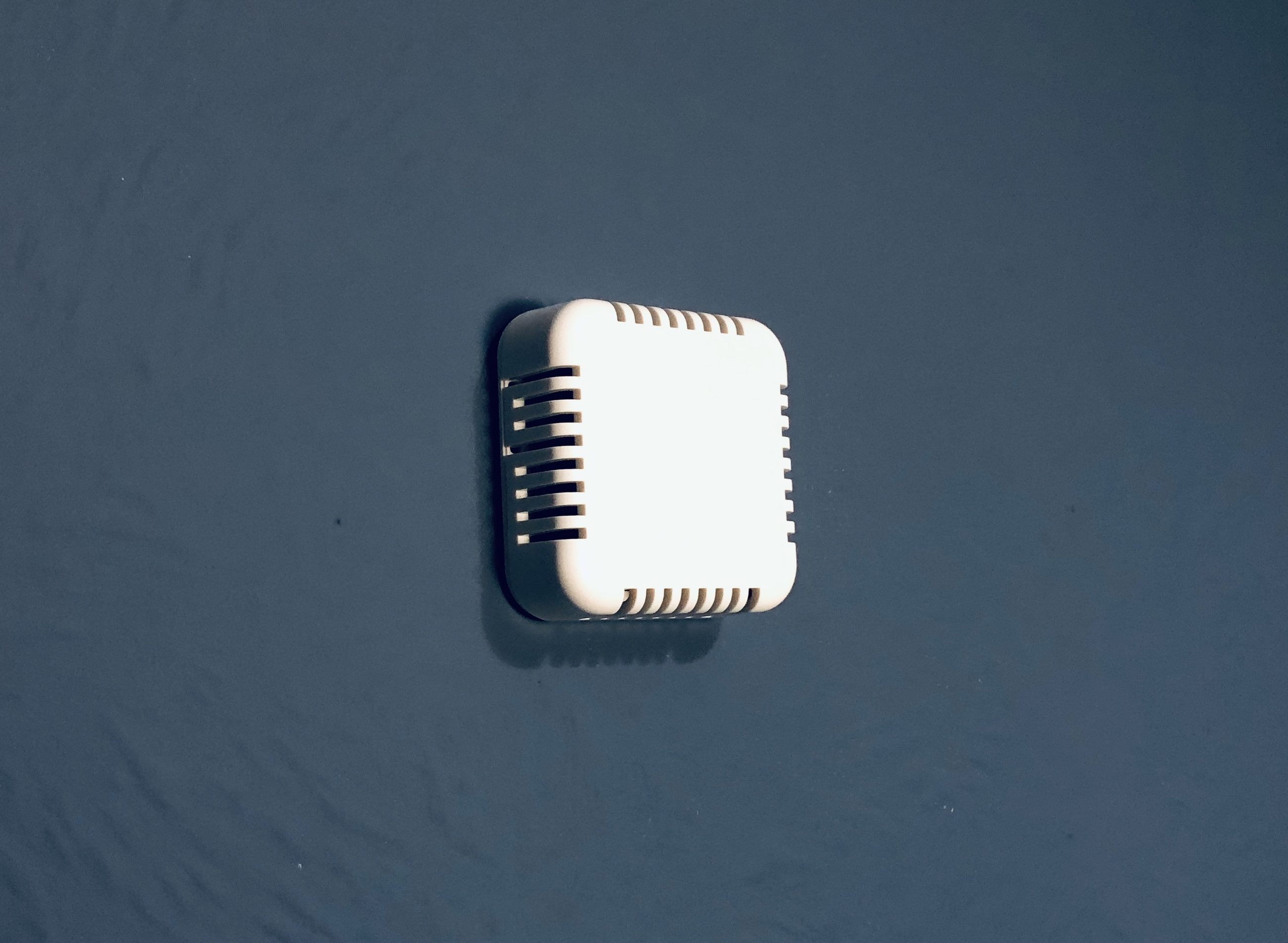
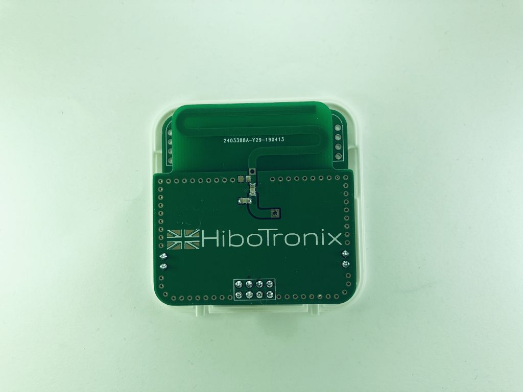
The Hammond 1551V3 enclosure was perfect, it looked the part and was designed exactly for the purpose so I ordered 5 and set about refactoring the PCB to fit inside. I knew because of its size and the fact it had to be coin cell powered I needed to use the lower-powered RFM69CW variant to get reasonable battery life. While reading the RFM69 datasheet I noticed the TX current requirement, at full TX power it could demand 45mA!
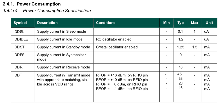
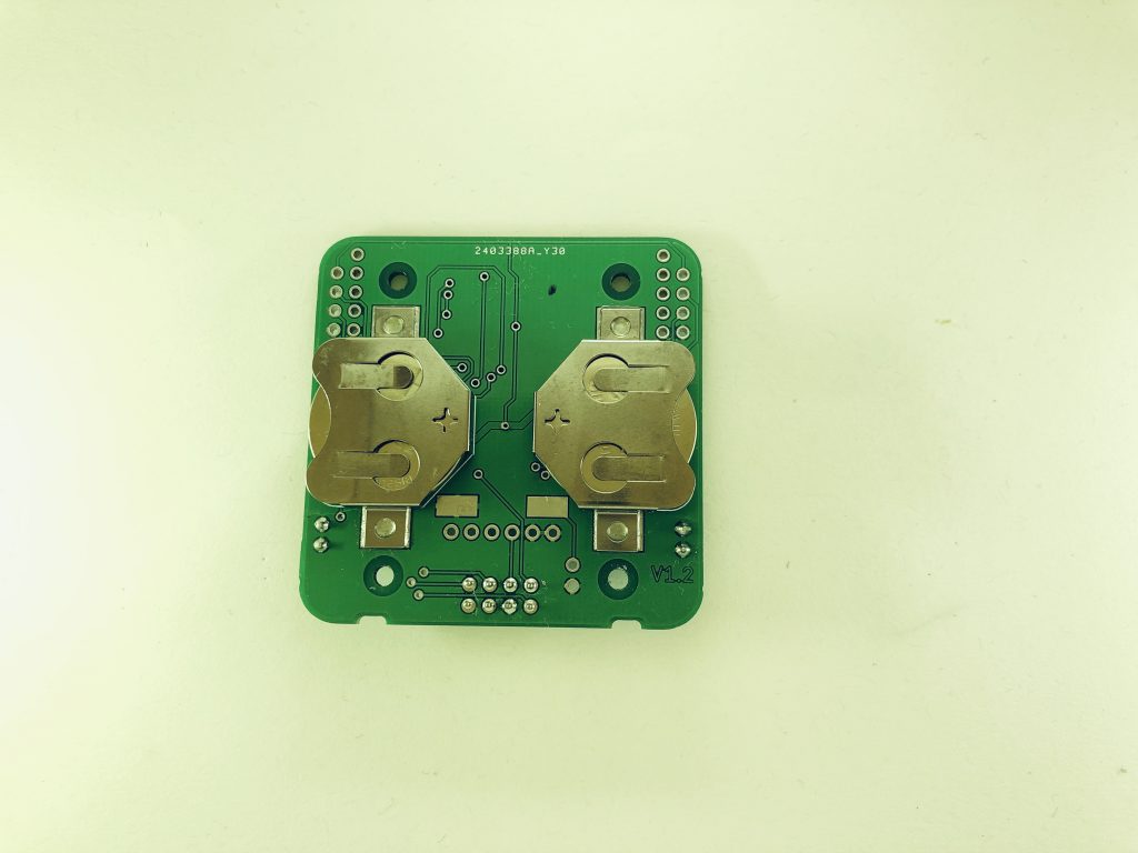
The requirement of 45mA from a CR2032 (which I had already chosen based on size and Power availability) was a bit much even to my basic knowledge in the battery arena. I looked at many datasheets but all the data for “Operating Voltage vs. Load Resistance” started at a minimum of a 1KΩ load, I needed ~67Ω load worst case!
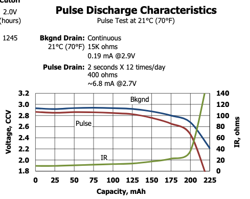
After careful testing and measurement with a working prototype, I concluded that 2x CR2032 cells in parallel would just about give me the pulsed load I needed with a negligible voltage drop on fresh new cells, considering the very short period of the TX pulse. The unknown, however, was how long these cells would last.
The brains of the operation were already chosen too, the venerable ATMega328P running at 8MHz maximum and utilizing LowPowerLabs Moteino Library by Felix Russo. Ths library includes a sleep mode when not transmitting bringing the quiescent current to ~6µA.
At this point in my journey, I had a working prototype with a wire antenna knowing that if I wanted to retain the almost professional look I wanted for a happy household I needed a better solution for an antenna.
The choice of antenna quickly boiled down to:
- Ceramic Chip Antenna
- Folded Metal Type
- Coiled Spring Type
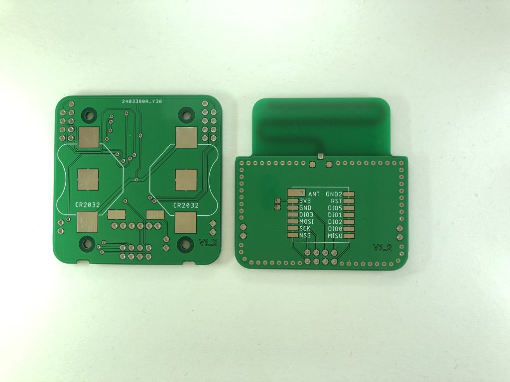
- PCB Antenna
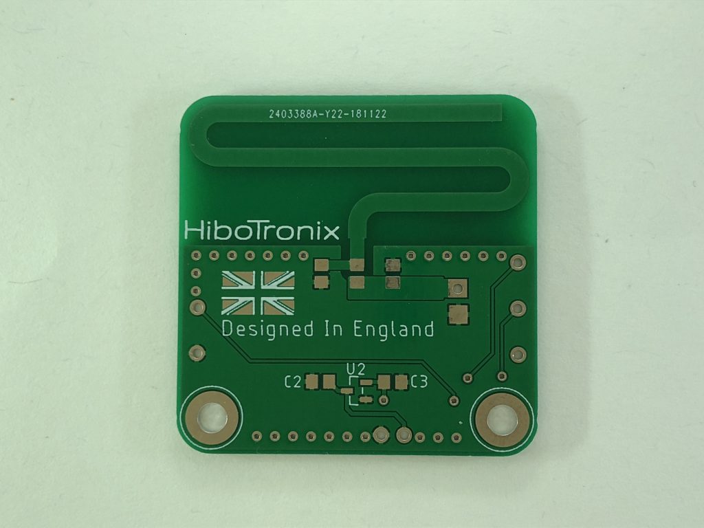
It soon became clear the choice of the antenna was going to be based on lots of variables, cost, size, the complexity of implementation etc. Somewhat risk-averse, and let’s face it, nobody likes failure, I opted to fail “fast and cheap” and settled on a PCB antenna. The almost endless information on the dark art of PCB antenna design started to consume all of my spare time so I chose a reference design based on a meandering monopole style. I carefully transposed the design onto my PCB and sent them for manufacture.
My plan, based on discussions with my like-minded maker friends was to order enough PCB’s to fulfil my requirements then sell the remaining on my Tindie store to recoup some of the costs of the project, in essence, making my sensors free! To accomplish this I needed to be confident that these devices performed as desired, the hardware was established but I feared the antenna was a weak point.
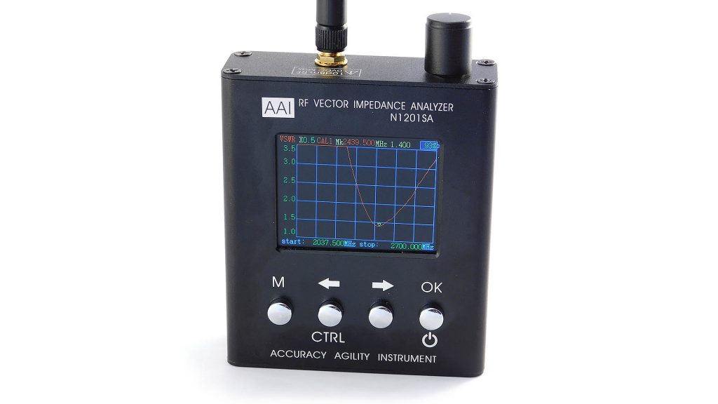
The first test of the newly assembled device was horrible, missing packets and a 6-8ft range. I had used a cheap Chinese Vector Impedance Analyser to test the PCB antenna knowing that getting my matching network even remotely in the ballpark would increase the range as other users of the RFM69CW had written of ranges in excess of 300ft line of sight. My range increased by 2-4ft but the packet loss was just as horrible.
It was time for professional assistance, my fail fast and cheap attitude went out the window, I don’t like to fail, but when I do I need to know how badly, hoping I was close, as to soften the blow. I found a particularly friendly RF Engineer near me who indulged my inexperience and helped me investigate.

The first reports were in, and they were as horrible as I imagined. From memory, it had a VSWR of around 12 which meant upwards of 70% of the power was being reflected. I failed spectacularly. The poor RF guy was probably as horrified as I was that such an antenna exists. I asked him to calculate the correct matching network and run it a second time.
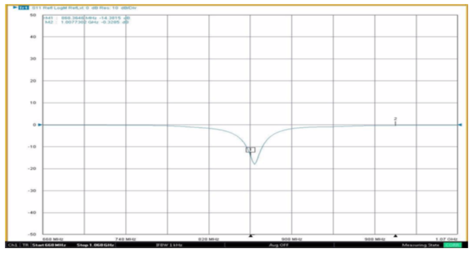
From my day job I was aware that anything under a VSWR of 2:1 was acceptable to most commercial installations I deal with so the sight of this familiar-looking dip was encouraging. Again from memory, the VSWR was around 1.5:1, excellent, but VSWR isn’t even half the story. To have reliable packet delivery I also needed a good bandwidth margin and also the radiation pattern needed would also have to be suitable for the intended application.
One of the observations from the RF guy was that while the antenna was “matched” inside the enclosure, removal of the front cover completely de-tuned the antenna, something he was fully aware of, but a valid lesson for an RF newbie like myself.
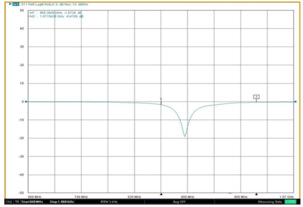
The antenna centre frequency shifted from 868MHz to ~900MHz by simply removing the cover, this just reinforced my new found respect for everything RF, a truly dark art. The bandwidth was about 15MHz which was OK but the RF guy said he frequently aims for, and achieves, 100MHz bandwidth for his regular customers. He also highlighted the fact that a “narrow” bandwidth also makes the component choice for the matching network quite important suggesting I used a tighter tolerance product.
Almost at the end of my RF adventure, I had to see the 3D plots of the radiation pattern, while researching PCB antennas I was greeted with almost perfect doughnut shapes radiating outwards, did I even manage it?

Yes, I did 🙂
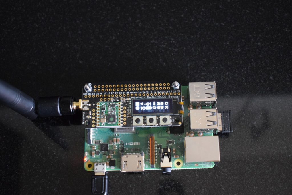
At the time of writing the Completed devices (2 of) have both been Working In my house on the same batteries and without a single missed packet since May 2019. They both report Temperature, Pressure and Humidity, every 15 Minutes to my Raspberry Pi 3 with an Adafruit Radio Bonnet.
Although the devices work for my needs, I made the decision not to offer these for sale, I don’t have the RF expertise to support my customers and although they work perfectly in the locations and at the distances I chose, I couldn’t guarantee they would work universally.
Would I start another RF project? Hell yeah, but I’d consult with a professional first!
Update: 8th February 2020
The batteries finally ran out today after 26781 packets, 279 days or ~6696 hours!
Based on my previous calculations of 50µA “average” current, I used 334.8mAh or 167.4mAh per cell much lower than the 225mAh per cell rating. (self discharge probably accounted for some of this).

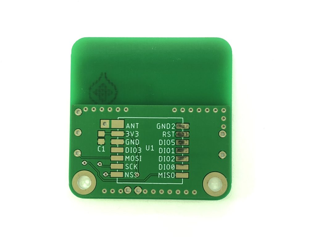
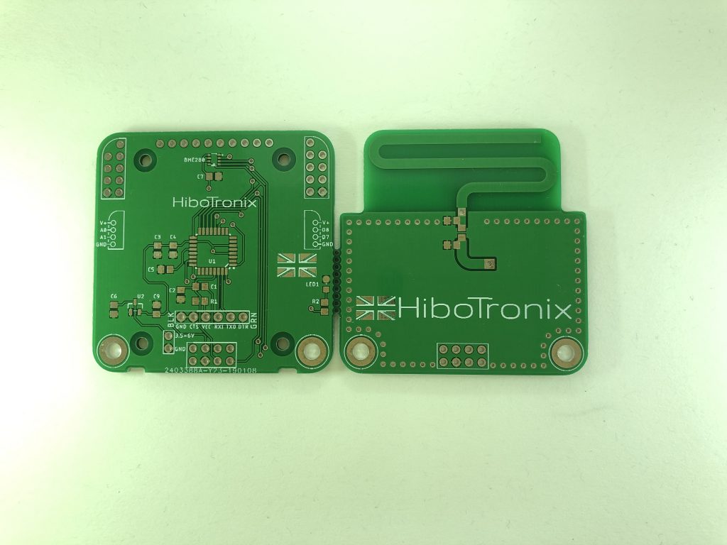
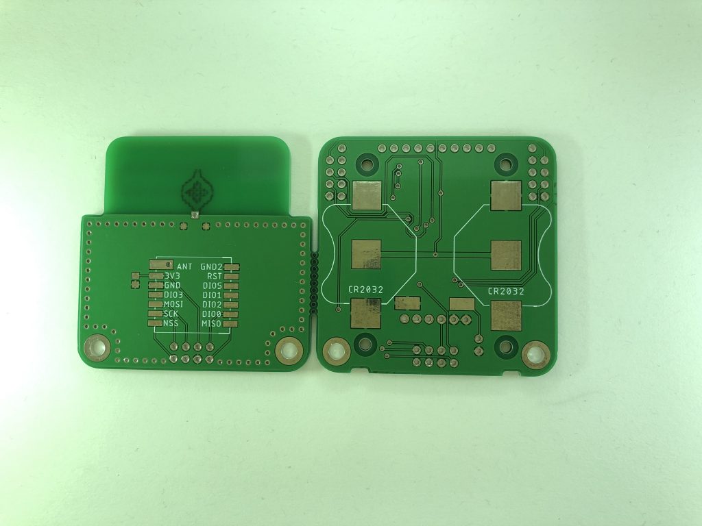
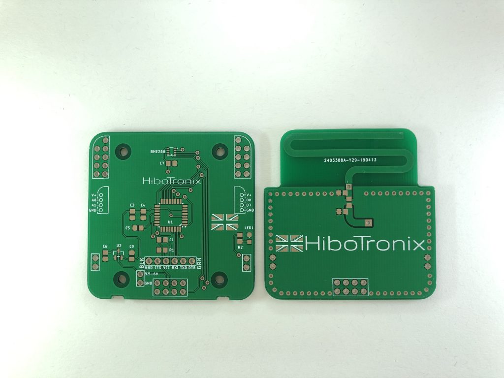
Revision 1 Front Revision 1 Back Revision 1.1 Front Revision 1.1 Back Final Revision Front Final Revision Back Final Revision Assembled Twin CR2032’s Front Cover Removed Raspberry Pi Gateway

Leave a Reply
You must be logged in to post a comment.